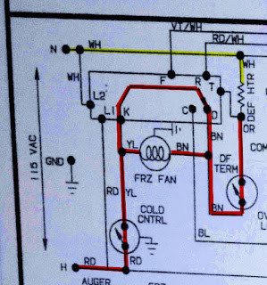
This diagram is a partial diagram of a residential refrigerator-freezer. It shows the defrost control, freezer fan, and defrost heat circuits. During normal operation the freezer fan is in series with the defrost heater, as shown in diagram 1. The heater has a resistance of around 28 ohms while the fan has a resistance of around 280 ohms. But since the fan is an inductive load, its total impedance (effective AC resistance) is much higher – more like 2800 ohms. The current for the circuit is very small 120 volts / 2828 = 0.04 amps. Voltage across each device is calculated by multiplying the current times the resistance. The heater voltage drop is 28 x .04 = 1 volt. The remaining 119 volts are all used by the fan. Essentially, the defrost heater is acting like a wire.
When the defrost control switch moves to the defrost position, the fan shuts off and the defrost heater energizes. The fan shuts off because now the same leg of power is applied to both sides of the fan. With no voltage difference from one side to the other, no current flows through the fan. The heater now has its own source of power ad receives a full 120 volts. The heater will stay energized until the defrost termination thermostat opens, breaking the circuit.
When the defrost control takes the freezer out of defrost (diagram 1) the fan will remain off until the coil is cold enough to close the defrost termination thermostat.


No comments:
Post a Comment