Showing posts with label basic electricity. Show all posts
Showing posts with label basic electricity. Show all posts
Wednesday, June 4, 2014
Defining Amps Without Ohm's Law
Here is a pretty basic question : What are amperes (amps for short)? Many folks will tell you using Ohm’s Law. However, defining volts, ohms, and amps in terms of each other is circular logic – it does not really explain what they are – only their relationship to each other. Amperes have a definition that does not involve Ohm’s Law. Amps are a measure of electrical current flow. The flow part is important. This means that time is involved. Amps are not really a quantity, but a rate. One amp is the flow of one coulomb of electrical charge per second. Note that the coulomb is the quantity and the ampere is the rate. Compared to gallons and gallons per minute (GPM), Coulombs are like gallons and amps are like gallons per minute (GPM). A gallon is a quantity – a specific amount of water. A gallon per minute (GPM) is that quantity of water moving in a minute. To have GPM, the water has to be moving and there is a time involved. Amps are the same way: the electric current must be moving and there is time involved. So what about Ohm’s Law? Well it is great for explaining the relationship of volts, amps, and ohms. I just find it useful to explain the concept of amps as a measure of current flow first.
Saturday, November 16, 2013
Electricity for HVACR
Pearson has released a new Electricity book by Joe Moravek titled "Electricity for HVACR." It shares the same overall structure as my book - lots of pictures and drawings with easy to follow text. It has short units and easy to follow organization. I have not read it end to end yet, but I have looked through several chapters - especially the ones on motors. I am impressed with what I have seen. If you are looking for a text to cover the electrical aspects of HVACR, you might take a look at this new book. You can learn more about it at the Pearson web site CLICK HERE
Monday, September 16, 2013
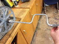
Hand Cranked Generator
I have had several people ask about building a generator students can turn by hand. I am putting a short explanation and several pictures on my blog. We built one using an ECM motor minus the module.

It puts out 3 phase AC. It is regulated only by the speed of the person turning it: you would not want to run your computer on it. To get enough speed we used a 12 inch pulley for the students to turn and a 1 inch pulley on the motor shaft: This produces 12 spins of the generator for every one revolution of the hand crank. I ordered the bearings, pulleys, belt, and shaft from Grainger.

We used heavy slotted shelving material to make the frame. This also came from Grainger - but it was left over from other projects.


We brazed a large hex nut onto a hub that mounts on the shaft and we turn it with a large socket on the end of a speed wrench.

 It has been working for years - just needs a little tightening and adjusting from time to time. Students can fairly easily get to 120 volts - until I turn on a light.
One change I would make - we mounted the bearings to a couple of pieces of slotted angle and it is too flexible - hard to align the bearings so they don't bind. Plus, the bolts holding the slotted metal are also the ones that have to be loosened and tightened to adjust the belt. I would replace that with a solid block of metal and then mount that block to the frame.

It took 2 of us about 4 hours to make.


We used heavy slotted shelving material to make the frame. This also came from Grainger - but it was left over from other projects.


We brazed a large hex nut onto a hub that mounts on the shaft and we turn it with a large socket on the end of a speed wrench.


One change I would make - we mounted the bearings to a couple of pieces of slotted angle and it is too flexible - hard to align the bearings so they don't bind. Plus, the bolts holding the slotted metal are also the ones that have to be loosened and tightened to adjust the belt. I would replace that with a solid block of metal and then mount that block to the frame.

It took 2 of us about 4 hours to make.
Sunday, September 6, 2009
Teaching Ohm's Law for Parallel Circuits

Subscribe to:
Posts (Atom)