Sunday, December 18, 2016

Refrigerant Line Sizing

Refrigerant line sizing is an overlooked aspect of system application and installation. Incorrectly sized refrigerant lines can rob your system of capacity and reduce its efficiency. In a worst case scenario, incorrectly sized and applied refrigeration lines can cause multiple compressor failures. For most applications, the two lines involved are the liquid line and the suction line. 

Pressure drop in the liquid line can create flash gas in the line before the refrigerant reaches the metering device. This causes a drop in system capacity because it reduces the amount of liquid entering the evaporator. Some pressure drop is inevitable. It is important to have enough liquid subcooling to offset the pressure drop through the liquid line. 

Suction line pressure drop also hurts the system performance by increases the compression ratio and reducing the amount of refrigerant being circulated. The general rule is to try and keep suction line pressure drop below an equivalent saturation temperature drop of 2F. The actual amount of pressure this represents depends on the refrigerant and the evaporator saturation temperature. Suction lines have another very important design criteria: the refrigerant traveling through them must have sufficient velocity to return oil. While larger lines help reduce pressure drop, they also decrease refrigerant velocity. In general, you want your suction line to be as large as possible while still having enough velocity to return oil. 

There are far too many variables to mention in a blog post, but I can point you toward some excellent materials available online. DuPont and Lennox both have excellent refrigerant piping handbooks available on the web in pdf form. The Dupont document is applicable to all forms of refrigeration while the Lennox material is primarily for air conditioning. Virginia Air has a great excel file which does a lot of the heavy lifting for you in calculating pressure drop and velocity. They also have several line sizing tables on another tab of the excel file. I guarantee that you will learn something about line sizing if you download and examine these three wonderful resources. I know I did.


Lennox

Virginia Air

Monday, December 12, 2016

Cold Weather Heat Pump Charging

Charging an air source heat pump during cold weather has always been a bit of a problem. The problem is that the amount of refrigerant circulated decreases as the outdoor temperature drops. Why is this? Well, as the outdoor temperature drops, the evaporator temperature has to drop in order to be able to absorb heat from the outdoor air. The lower evaporator temperature produces a lower evaporator pressure. The lower evaporator pressure increases the compression ratio because there is now a greater difference between the suction pressure and the discharge pressure. The higher compression ratio means that the compressor does not circulate as much refrigerant.

At a 45°F outdoor temperature,  a typical air source heat pump produces a heating capacity roughly equal to its nominal cooling capacity. At 17°F outdoor ambient, it produces about half as much heat as it does at 45°F. This difference in capacity is directly related to the amount of refrigerant being circulated. The rest of the refrigerant is just sitting somewhere – normally in either the accumulator or the charge compensator. So a system operating at 17°F outside could have perfect pressures even if it only had half of its factory charge. That is why you can be way off checking a heat pump by pressures in the heating mode.

Some manufacturers provide heating performance pressure charts, but refer to them as “check” charts. They are intended to check the system operation at specific conditions, but are NOT intended as guides for adding refrigerant. The problem is that you don’t have a good way to judge how much refrigerant is stored out somewhere in the system. I can hear a bunch of you saying that measuring superheat and/or subcooling solves that problem. While I AM a fan of checking both, they still just measure the refrigerant that is circulating.

There have been some interesting methods used, such as measuring discharge superheat. For discharge superheat, you measure the temperature and pressure of the discharge line right as it leaves the compressor. It should be somewhere around 60°F warmer than the discharge saturation temperature. So if you have a 410A system running at a discharge pressure of 318 psig (saturation temperature 100°F), the discharge line should measure 160°F. A lower temperature reading indicates an overcharge and a higher temperature reading indicates an undercharge. The surest way to charge a heat pump in the winter is to recover the refrigerant, evacuate the system, and weigh in the correct charge. If you have performed a repair on the refrigerant system, then this will save you time and insure a correct charge.

Saturday, December 3, 2016

Cranking Out The Rules

 With only weeks left in the Obama administration, federal agencies such as the Energy Efficiency and Renewable Energy Office (EERE) are finishing up work on a number of initiatives and publishing final rulings. Who are the EERE? They are a subset of the Department of Energy (DOE). These rulings have an impact on the HVACR industry. While the rulings do not have a direct effect on technicians in the field, they have a big effect on HVACR manufacturers. Indirectly they will affect us as manufacturers respond to the directives. Most of the rulings have to do with how different equipment is tested by the manufacturer, and in some cases, what equipment is covered.  Here is a list of recent rulings with links for more information.

12/02/2016 DOE Issues a Notice of Final Rule Pertaining to Test Procedures for Walk-in Coolers and Walk-in Freezers

12/01/2016 DOE Issues a Notice of Final Rule Pertaining to Test Procedures for Compressors

11/30/2016 DOE Issues a Final Rule Pertaining to Test Procedures for Central Air Conditioners and Heat Pumps

11/21/2016 DOE Issues a Comment Period Extension Pertaining to Energy Conservation Standards for Residential Furnaces

 11/15/2016 DOE Publishes a Final Determination of Compressors as Covered Equipment

11/10/2016 DOE Publishes a Final Rule Pertaining to Test Procedures for Commercial Packaged Boilers

10/07/2016 DOE Issues a Final Determination Pertaining to Energy Conservation Standards for Direct Heating Equipment  

10/04/2016 DOE Issues a Direct Final Rule Pertaining to Energy Conservation Standards for Miscellaneous Refrigeration Products

Tuesday, November 22, 2016

Check Combustion Air

With the weather getting cooler, I thought that now would be a good time to talk about combustion air. Don’t forget to check for proper combustion air. Most codes provide detailed drawings illustrating where combustion air should come from and how much you need, but there are still many furnace installations that rely entirely on air from inside the building for combustion air. In days gone by this was often considered adequate so long as the furnace was located in a large enough space. In newer homes, combustion air should always be provided.

Most 90%  furnaces today can operate using sealed combustion. In the case of a sealed combustion furnace, the combustion air is being piped in from the outside. The combustion air is piped directly into the furnace. These are easy to spot, they have two pipes: one for combustion air and one for the vent. Also, their panels have no louvers for combustion air. 

Traditional furnaces get their combustion air from the space where they are installed. Combustion air enters through louvers in their panels.Since the furnace is drawing air from the space it is in, fresh combustion air must be supplied to the room to keep the process going. Failure to supply the correct amount of combustion air can lead to negative room pressure, vent spillage, poor combustion, and CO production. All these things together can be disastrous.

When a technician checks a furnace that does not have sealed combustion, one of the first things to look for is how the furnace receives combustion air. If the furnace is in a ventilated crawlspace or attic, the ventilation for those spaces provides the combustion air. However, even these can be a problem. A large furnace in a small crawl space may not have adequate combustion air if the crawl space vents are closed. I have also seen crawlspace vents clogged with debris, effectively reducing the combustion air.  

The most troublesome installations are furnaces located inside the house in a closet. They should have a combustion air vent near the floor and another near the ceiling. Someone asked me about a furnace installed in a closet off of a bathroom. When they turn on the bathroom vent fan, they can smell gas! Another story involved a fireplace and a furnace. When the furnace came on it sucked the smoke out of the fireplace into the room. These types of stories indicate that the furnace does not have adequate combustion air. 

What if there are no obvious combustion air vents? Sometimes the vents were never provided, other times they have been covered up. I have seen combustion air vents covered with tape or plastic. Undoubtedly, someone noticed cold air coming in the vent and “fixed” the problem – thereby creating a combustion air problem. Occasionally insulation covers the grille into the attic. Another problem is using the furnace closet for storage. This is dangerous in and of itself, but it can also cause combustion air problems if boxes are stacked in front of the combustion air grilles.  For details on combustion air requirements check your local code. Unit 53 Gas Furnace Installation in Fundamentals of HVACR, 3rd ed also has detailed drawings and specifications for the most common applications.  

Saturday, November 12, 2016

Veterans Have the Right Stuff

On this Veteran’s Day I would like to suggest a way that the HVACR Industry can help those who served their country: offer them jobs. Veterans have many characteristics that make them ideal employees.

Veterans are disciplined.
Veterans have developed both self discipline and group discipline – both crucial skills for employment.

Veterans know how to work hard.
Remember, they made it through boot camp and survived years of living conditions most of us would find intolerable, all the while performing their job.

Veterans know how to be a team player.
The armed forces cannot function if everyone is freelancing. Installation is so much easier if you have a good team. Far more efficient than working alone.

Veterans can master technically difficult machinery.
Take a look at the equipment today’s armed forces work with. Much of it is incredibly complex. A veteran is someone who has been in a position where their life depended upon knowing how to operate that machinery.

Today, finding people who are good candidates for employment in the trades can be tough. Veterans already have the traits employers look for in a good employee, and that is a good base to build on. If the industry will reach out to veterans we will also help ourselves.

Here are links for people considering hiring a veteran or for veterans looking for help getting started in HVACR.

Troops to Trades 
Nexstar Legacy

Sunday, November 6, 2016

Digital Data Recording and Reporting

A relatively new class of communicating digital tools makes it possible to share your readings electronically. They not only take accurate pressure and temperature readings, they can share those in an email with your supervisor, company, customer or energy utility. And many of these can take more than just refrigerant pressure and temperature readings. The Stride I-Manifold, Testo Smart Probes, Fieldpiece System Analyzer, Sporlan Smart Tools, Yellow Jacket Mantooth, and Appion ION gauges can all send data to your electronic devices, which then use free applications to create and send the reports. Some can collect information from a variety of instruments and report on them as well. For example, you can also get ambient temperature, indoor wet bulb, and indoor airflow. I am sure I probably missed a few.  The point is, tools are available now that can do more than collect data; they can help you organize it and report your results.

The reporting capability allows you to document what you have done. For example, you can produce before and after reports showing the system performance when you arrived and the system performance after you have made adjustments. You can also send reports to your supervisors if you need help. Some utilities have rebate programs which require that the contractor use a particular reporting setup. The idea is that the utility can verify that the system really is performing as designed by the manufacturer.

This is both exciting and a little bit intimidating. Until now, if you went on a call and checked the system performance, you were generally the only person that would see all the measurements and make the judgement. If you have checked more than a handful of systems, you know that checking system performance really is a judgement based on a lot of variables. And, you only have control of a few of those variables. It is not as simple as matching a couple of pressures and temperatures.

There is the outdoor temperature, the indoor temperature, the indoor wet bulb, the airflow across each coil; any one of which can make your system perform in a way you don’t expect. That is before issues such as plugged expansion valves, restricted filter driers, underperforming compressors, or installation errors. All of these things must be verified before adjusting the charge. It would be nice if we could just state a couple of pressures and/or temperatures and leave it at that, but that is not reality. Even manufacturer performance charts and tables assume a lot of this information. If just one value is off from the assumption, the manufacturer’s chart will not work.

So, if you ever needed any incentive to up your game when checking systems, having to send reports to supervisors, utilities, and customers should do the trick. Beer-can cold is just not good enough in an environment that expects documentation and verification. That is unless you plan to strap a can of Coors to the suction line and send in a photo of the color change. Here are a few links to check out these new-age tools.

Appion - http://www.appioninc.com/products/ptgauges.html
Fieldpiece - http://www.fieldpiece.com/products/detail/sman460-wireless-4-port-digital-manifold-with-micron-gauge/system-analyzers/
I-Manifold - http://imanifold.com/
Sporlan - https://sporlanonline.com/smart/
Testo - http://www.testo.us/smartprobes/index.jsp
Yellow Jacket - http://yellowjacket.com/product/mantooth-dual-pressure-wireless-digital-pt-gauge/

Friday, October 28, 2016

What is an HFO?

Hydrofluoroolefins, HFOs, are a relatively new class of low global warming potential refrigerants. They are actually composed of the same chemicals found in an HFC: hydrogen, fluorine, and carbon. If you define an HFC as a chemical containing those three elements, then HFOs are actually HFCs. The difference is in how they are constructed.
Ethane
HFC 134a
 Both HFCs and HFOs start out as a hydrocarbon, containing a chain of carbon atoms surrounded by hydrogen atoms. To make a traditional HFC you replace some of the hydrogen atoms with fluorine atoms. Standard hydrocarbon molecules and traditional HFC molecules are composed exclusively of single atomic bonds. You can think of an atomic bond as a type of Velcro strip holding the atoms together. Carbon has four atomic Velcro strips while hydrogen and fluorine just have one. Single bonds just attach one strip between atoms. Using only single bonds a carbon atom will connect to four other atoms because it has four bonds. Molecules constructed this way are called saturated. They have the maximum number of atoms joined together.
Propane


HFO 1234yf
What makes HFOs different is that they use a double bond between two carbon atoms. These two caron atoms are connected together with two Velcro strips instead of just one. Since carbon atoms only have four connections, using two to connect to each other means that each carbon can only connect to two other atoms besides each other. This reduces the total number of atoms that can be connected together. This type of molecular construction is called unsaturated.

Why does this make a difference? Unsaturated molecules are far less chemically stable and tend to break down easier. Since HFOs are less chemically stable, they do not survive long in the atmosphere – and so they do far less harm than the more stable saturated HFCs. The difference is dramatic. HFC 134a has a GWP of 1430 while HFO-1234yf has a GWP of 4.

However, HFOs have a design challenge to overcome: they are mildly flammable. The very instability that reduces their GWP increases their flammability. At present, building codes in the US generally do not recognize a difference between highly flammable refrigerants and mildly flammable ones. Most building codes do not allow the use of significant amounts of flammable refrigerant inside the building. ASHRAE is working on revising their Safety Standard for Refrigeration Systems,  Standard 15. It is projected to be ready by January 2018. For more information on the work being done on flammable refrigerants check out this article in Contracting Business
http://contractingbusiness.com/refrigeration/codes-preparing-technology-refrigerant-changes

Saturday, October 15, 2016

Personal Gas Safety

Time for furnace tune-ups is here. Soon you will be taking the first no-heat calls of this heating season. No doubt you will be inspecting equipment for safety concerns that affect the customer. Don’t forget to pay attention to your own personal safety. Gas leaks, leaky vent systems, incorrect combustion, and lack of combustion air can all create immediate hazards to the service tech working on the system. There are pro-active steps you can take to stay safe while working on gas fired equipment.

Gas Leaks
If there are existing gas leaks it is possible that a combustible atmosphere exists in the space. Ideally, you want to check the air in the space for combustible gas before entering. You can use an electronic combustible gas detector for this. Many techs now use these to check for gas leaks, so you might already have the tool. Just turn it on and let it sample the air in the room as you enter. There are also personal detectors which you can wear to monitor the conditions wherever you are. If you do detect combustible gas in the room, do NOT turn on or off any electrical switches and leave the room. Shut off the gas outside and ventilate the room before continuing. You will have to turn the gas back on to find the leak, but you can ventilate the room and start with a safe atmosphere while you are doing it.

Carbon Monoxide
Negative room pressure, incorrect or leaky gas venting, and lack of combustion air can all contribute to a build-up of carbon monoxide in the room. You can’t smell or see carbon monoxide, so it is especially dangerous. Again, you should test the atmosphere in the room. There are electronic detectors made to check for carbon monoxide in the air, and some are made to wear to monitor the air continuously. If the monitor indicates a build-up of CO in the room, you should shut off the gas outside the room and ventilate the room. Once the room is cleared of CO you can start to look for the cause. Before turning the gas back on make sure to check for obvious things such as blocked combustion air intakes or compromised gas vents. After restarting the furnace you should check the flame color and test the flue for proper operation. Also be sure to check the flue gasses for CO.

Gas Ignition Problems
When observing a gas furnace light, you should never place your face directly in front of the furnace. If there is a delayed ignition or flame roll-out you can be inside the fire-ball. I have made that mistake. It was over before I knew what happened. For a second all I could see was yellow because my head was in the fireball that came out of the furnace. Luckily it just singed my eyebrows a bit and gave my face a slight burn similar to a sunburn. Afterwards I worked out what had happened: a leaky gas valve had allowed a build-up of gas prior to turning the furnace on. Had my face been off to the side I would not have been in the flames when they came out.


Don’t leave your personal safety to chance. 
Take steps to detect and avoid possible personal safety hazards. It is an inconvenience to the customer to have to call 911.


Friday, October 7, 2016

Sorting Out Refrigerant Flammability

Most techs know that ASHRAE Standard 34 originally established three categories of refrigerant flammability: 1,2, and 3. They ranged from 1 – nonflammable, to 3, highly flammable. Category 2 was listed as mildly flammable, or somewhat flammable. Then they added a new category – 2L – for an even lower category of still flammable refrigerant. I admit that I always found that a bit confusing. In my mind, it either burns or it doesn’t.  In order to get a better handle on this I have done some studying.

Two characteristics are used to differentiate category 1 and category 2 refrigerants: the lower flammability limit and the heat of combustion. The lower flammability limit is the lowest percentage concentration of gas in a gas-air mixture that will ignite. Concentrations lower than the lower flammability limit will not burn. Even highly combustible gasses such as gasoline have a lower flammability limit. Refrigerants with a lower flammability limit of 3.5% or less are considered class 3, highly flammable. For comparison the lower flammability limit of gasoline is 1.4%  and propane‘s is 2.1%. Another way for a refrigerant to be considered class 3 is for its heat of combustion to equal or exceed 19 million joules per kilogram. In general terms, it does not take very much class 3 refrigerant to burn and when it does it is very hot.

Class 2  refrigerants have a lower flammability limit greater than 3.5%. It requires more than 3.5% concentration in order to ignite. Class 2 refrigerants do not burn as hot as class 3 refrigerants: their heat of combustion is lower. The lower heat of combustion is important because that is what sets other things on fire. It is possible for a class 2 refrigerant to burn without burning up everything around it.

So where does the 2L come in? Flammability class 2L is really a subclass of 2. Refrigerants with a 2L designation have a burning velocity of 10 centimeters per second or slower. The burning velocity is how fast the flame travels. A burning velocity of 10 cm/s means that the flame will travel about 4 inches in a second. In contrast, the class 2 refrigerant HFC-152a  has a burning velocity of 23 cm/sec.  – a little more than twice as fast.  Propane, a class 3 refrigerant, has a flame velocity of 39 centimeters per second – 4 times as fast.

Why is this important? The flame velocity and heat of combustion are what determine whether or not an explosion can occur. Rapid burning and high heat of combustion expand the air and combustion gasses so rapidly that great pressure is created, blowing things apart. Class 2L refrigerant cannot burn fast enough or hot enough to blow anything up. In many cases, a burning class 2L refrigerant will not even catch other combustible things around it on fire.

To summarize:
Class 3 Refrigerants have a lower flammability ratio of 3.5% or lower and/or a heat of combustion equal to or greater than 19Mj/kg. They burn fast and hot.

Class 2 Refrigerants have a lower flammability ratio exceeding 3.5%. It takes more of them to burn and they do not burn as hot as class 3 refrigerants.

Sub-Class 2L Refrigerants in addition to a lower flammability ratio exceeding 3.5% also have a flame velocity of 10 cm/sec or less. They burn slowly and without releasing as much heat.

Class 1 Refrigerants do not burn.


Friday, September 30, 2016

New EPA Rules

On September 26, 2016 the EPA issued a new Final Ruling updating the regulations for handling refrigerants. Don’t panic, there is plenty of time to prepare. For technicians, the first important enforcement date is not until January 1, 2018 and some parts do not take effect until January 1, 2019. However, you do need to prepare. There are more changes than I can list in a short blog post, but I will provide an overview and plenty of links to the information.

Mostly about Global Warming
Most of the changes have to do with limiting global warming by reducing the use and release of HFC refrigerants. Some of the more significant changes include requiring certification to purchase and handle HFC refrigerants, reducing the allowable leak rate for ozone depleting and global warming refrigerants, specifying regular leak inspection for equipment which has exceeded the allowable leak rate, and requiring record keeping when disposing of systems with more than 5 pounds of refrigerant.

Technician Certification
Staring January 1, 2018 technicians must be certified to purchase and handle nearly all refrigerants, not just ozone depleting ones. One curious exception is that sales of small cans of refrigerant for use in car air conditioning systems will not require certification. The cans will be required to have a valve, but sales to the general public will still be allowed.

Leak Rates Lowered
Starting January 1, 2019, the leak rates will all be lowered and will apply to HFC and replacement refrigerants as well as ozone depleting refrigerants. A few specific refrigerants are exempted from the venting prohibition and the leak requirements. These exempted refrigerants include carbon dioxide, nitrogen, water, ammonia, chlorine, hydrocarbons, and R441A. The leak trigger rates which require repair are now 30% for industrial process refrigeration, 20% for commercial refrigeration, and 10% for air conditioning and “other” uses. Note that the refrigerant charge level for these trigger rates remains at 50 pounds or more.

Leak Inspection
Beginning January 1, 2019, the new rules require regular leak inspection for systems that have reached the “trigger rate” requiring leak repair. The frequency of the required inspections is determined by the type of system and the size of the system charge. Quarterly inspections are required for commercial refrigeration and industrial process cooling systems which hold 500 pounds or more refrigerant. Commercial refrigeration and industrial process cooling systems holding at least 50 pounds of refrigerant but less than 500 pounds require an annual leak inspection. Air conditioning systems holding at least 50 pounds require annual leak inspections. When leaks are repaired, an initial system tightness verification is required before adding refrigerant. A second system tightness verification is required after the system is up and operating. Records of all of these tests are required.

System Disposal Record Keeping
Starting January 1, 2018 technicians disposing of systems with at least 5 pounds of refrigerant must keep records regarding the equipment and the refrigerant charge. Specifically, you must keep
The location, date of recovery, and type of refrigerant recovered for each disposed appliance
The quantity of refrigerant, by type, recovered from disposed appliances in each calendar month;
The quantity of refrigerant, and type, transferred for reclamation or destruction, the person to whom it
was transferred, and the date of the transfer. Note that you are not required to report the quantity of refrigerant recovered from each individual system, but rather, the cumulative quantity of refrigerant recovered each month.

Links to EPA Documents
This is just an overview. To really understand all the details you should consult the information published by the EPA. Here is a list of links to some of that information.

Advance Copy of Final Rule
https://www.epa.gov/sites/production/files/2016-09/documents/608_final_rule_pre-publication_copy.pdf

Subpart F—Recycling and Emissions Reduction
http://www.ecfr.gov/cgi-bin/text-idx?SID=085a41355598f2919b6655098a466757&mc=true&node=sp40.21.82.f&rgn=div6

Fact Sheet on New Regulations
https://www.epa.gov/sites/production/files/2016-09/documents/608_fact_sheet_technicians_0.pdf

EPA Page on Revised Regulations
https://www.epa.gov/section608/revised-section-608-refrigerant-management-regulations

EPA page on leak requirements
https://www.epa.gov/section608/stationary-refrigeration-leak-repair-requirements


Friday, September 23, 2016

HFCs not Going Anywhere

HFCs are not going away any time soon. I am sure you have all hear about the push to reduce or eliminate HFC refrigerants because of their global warming potential. This past weekend at Comfortech 2016 I sat in on a very informative session by Rob Yost on refrigerants. One big point was that low GWP replacement candidates for R410A are all rated at 2 or 2L for flammability. The reason is pretty straight forward. To be non-flammable a chemical must be relatively stable. However, that stability means it lasts longer in the atmosphere, which increases its global warming potential. In other words, low flammability and low global warming potential are somewhat opposites in terms of chemical properties.

The newest low GWP blends being developed are actually blends of both HFOs and HFCs. The highest pressure HFO developed at this time is very similar in pressure to 134a. Obviously that won’t replace 410A. However, mixing it with some higher pressure HFC refrigerants yields a much lower global warming potential than 410A at working pressures that are similar to 410A. However, this mixture will be flammable.

The current building codes in the US don’t allow flammable refrigerants inside buildings in most circumstances, so none of the refrigerants presently being studied can be used under the current building codes. The next revision for building codes is due out in 2018. However, the window for incorporating exceptions for lower flammability refrigerants into the 2018 code has already passed – and no exceptions or conditions for the use of 2L flammable refrigerants are in the upcoming 2018 code. That makes 2021 the closest date that flammable refrigerants could possibly be used inside buildings. Even though that is only a little over four years from now, we can be reasonably sure that no mass extinction of HFC refrigerants will occur any time soon.

Before we transition out of 410A to something else, the issue of using lower flammability refrigerants inside buildings will have to be addressed, and even then, it is likely that HFC refrigerants will be some of the components in the next generation of refrigerants.

Friday, September 16, 2016

Are You Keeping Up?

Technology is changing the HVACR industry so quickly that many techs get vertigo from the dizzying changes. It is tempting to try and “opt out” of the technological revolution and stick to the old familiar technologies you are comfortable with. However, your lack of participation will not slow the train, you will simply be left behind.

Before heat pumps were common in the southeast, I remember many techs declaring that they would not work on heat pumps. Today, any tech in Georgia who does not work on heat pumps does not work very much. I remember another time an older tech  telling a story of how he retrofitted a system with a stack control and threw away that electronic junk. So the customer ended up paying a lot to downgrade their system because the tech did not understand it. Worse, it did not work well afterwards.

I know many techs today are leery of communicating control systems, variable refrigerant flow systems, electronically controlled compressor motors, and WiFi thermostats – just to name a few things. These things are not going to go away. Customers like them. They like the energy efficiency and convenience these products bring. If you don’t sell and service them, someone else will. The only logical course of action is to educate yourself on the emerging technologies found in the HVACR industry. This is a lifelong process. This year is not the same as last year, and there will be more to learn next year. I am older than most practicing HVACR techs, but I do not long for the “good old days.” I am too busy having fun with the new toys, there is just so much I need to learn.

Sunday, September 4, 2016

Primary and Secondary Drain Connections

Have you ever wondered why evaporator coils often have several drain connections? It is not because the manufacturer had extra PVC drain plugs they needed to use. Most coils have both primary and secondary drain connections. Sometimes they have more than one set for convenience, and sometimes they have multiple sets because the coil can be positioned more than one way. It is important to recognize the difference between a primary and secondary drain connection and pipe them correctly.

The secondary drain provides an outlet for the water in case the primary gets plugged up. Since the secondary connection is a backup drain, it is located slightly higher than the primary connection. Sometimes this is done using an internal dam which forces water to go through the primary drain unless it is plugged up.
Primary drain on the right and secondary drain on the left.
Notice the internal dam on the secondary drain connection.

Most manufacturers recommend that the primary drain be trapped, but the secondary is typically not trapped. The secondary and primary should not run to the same drain line. If the drain line gets plugged up and both drain connections run to it, there is really no point in having a secondary drain connection. Often, the secondary drain line runs  very short distance to an overflow drain pan or a condensate pump.

Another way to utilize the secondary drain connection is to install a condensate overflow switch on the secondary drain connection so that the system shuts down if water builds up to that level. I like that because the customer knows there is a problem and calls for a correction. If the secondary drain handles the water without incident it might not be noticed until it stops up as well.

Overflow switch connected to secondary drain connection on the left.

I saw a system this summer which was several years old and had never been piped correctly. The primary and secondary drain connections had been swapped. The primary drain was piped to an overflow drain pan under the unit  and the secondary drain was connected to the actual condensate drain line which was completely dry and clean. The overflow pan was full of brown slime, and the drain to that overflow pan had stopped up and the water was now overflowing into the ceiling. The difference in the two drain connections was obvious – the secondary drain connection was located higher. But maybe not so obvious to the installer. Just know that there is a reason for the two connections: one is for your primary drain and the other is to avert disaster. If you get them confused you are creating a future problem.

Friday, August 26, 2016

Keep Your Cool

This week I am passing along a tip contributed by a reader, Mike Lilley. He keeps cool by wearing a cooling vest. After doing a little research I found three types of vests for sale: one that circulates air, some that use evaporation, and some that use phase change gel. For attic work I think we can rule out the air vest because it works by circulating ambient air through the vest. In dry heat the evaporative vests should work well, especially outside. However, in an attic in the southeast, I think their performance would not be enough to keep you cool. Mike said that the workers at his company use cooling vests with phase-change gel packs.

The gel packs are similar to the blue-ice packs you might use for your cooler, with one big difference. This gel freezes and melts at 58°F. Remember that the temperature of a substance stays the same as it changes state. This is an important concept in making air conditioning work. This gel stays at 58°F until all of it has melted, and 58° is comfortable, as opposed to keeping a 0°F gel pack next to your body. Further, you can freeze the removable gel packs in a refrigerator or in a cooler with ice. A couple of users commented that it is important to keep the packs flat during the freezing process. Otherwise, the hard, lumpy gel packs make the vest uncomfortable. Here is a link to learn more about these cooling vests. I must tell you that I have not personally used one – yet. But is certainly sounds like a cool idea.

Here are a few links to learn more about cooling vests.  
https://www.amazon.com/TECHKEWL-Phase-Change-Cooling-Vest/dp/B0002EWKTS
http://www.coolvest.com/
http://www.mycoolingstore.com/cooling-vest.html

Saturday, August 20, 2016

Attic and Crawlspace Safety

In the last post I talked about a tech succumbing to the heat in an attic. Since the service business is about solving problems, not simply presenting them, I have been looking for solutions to tech safety. Bill Spohn of TruTechTools contacted me and offered a solution to prevent heat exhaustion and heat stroke. His company caries a line on skin patches called “HOTDOTS” that change color from black to yellow if a person starts to overheat. Each patch is a one-use patch good for one day. They come in pack of 6 for about $!6. So you can protect yourself from overheating for $16 a week – not bad. Here is a link http://www.trutechtools.com/HD6

His company also carries a full line of atmospheric gas safety monitors which can check for things such as oxygen and carbon monoxide. Here is a link to those
http://www.trutechtools.com/Atmospheric-Gas-Hazards_c_1907.html

If you are working on combustion equipment you really should have an atmospheric CO detector with you to insure the space you are working in does not have a dangerous buildup of CO. I would not trust the inexpensive detectors you buy in big box stores. They often have a long delay before alarming, even at levels that can be dangerous.  You need something that displays the CO level so you can test the space when you first enter without relying on an alarm.

A combustible gas detector is also advisable. You don’t want to enter a space that has a buildup of combustible gas. In the old days of halide torches I narrowly avoided being a statistic of an explosion caused by a gas leak. I was going to enter a crawl space to check for a refrigerant leak with a halide torch. I waited to light the torch until I actually got under the house, which probably saved my life. When I approached the crawl space door I smelled gas, so I did not light the torch. The odd thing was that there was no gas equipment under that part of the house. I followed my nose across the yard to a large LP tank with a bad leak where the line came out of the regulator. The LP being heavier than air had drifted downhill 50 feet across the yard and collected in the crawl space. I fixed the leaking flare and told the home owner what I had found. They said they had just received a delivery the previous day. Had I not paid attention to my combustible gas detector (my nose) there might not have been a “Fundamentals of HVACR” because one of the authors would have perished decades before. It is always a good idea to test the spaces you plan to enter. To be in a position to help anybody else you must first insure your own safety.

Wednesday, August 10, 2016

Heat Can Kill

When you think about the dangers of working on air conditioning equipment, you probably think about working with electricity, refrigerant, and torches. We often overlook a more obvious danger: the weather. The reason we have a job is because it is either hot or cold. A recent tragedy in Lubbock Texas highlights the dangers of working in attics in the summer. An HVAC worker was found unconscious in an attic and subsequently died. Here is a link to the local area news about the incident. Lubbock Tragedy

It is very important to be aware of the danger that hot and cold extremes can pose to workers. One of the most important aspects of safety when working in the heat is to keep hydrated – drink lots of water – and drink often. Evaporation of sweat is your body’s last available cooling mechanism. It is very effective provided that you keep the flow of water into your body. 

Air movement helps by accelerating the evaporation of the sweat. If possible, set up some type of fan to help move air in the attic space. I have known mechanics to disconnect a few duct runs and run the air conditioner to keep the attic cool. Of course this only works if the unit is working. 

Another way to avoid life threatening consequences of working in hot attics in the summer is to work early – preferably before noon. If someone really wants their AC working, they won’t mind letting you start work at 7:00 AM.

You must monitor your body’s reaction to the heat. If it is hot and you are NOT sweating, you should get out of the attic and hydrate. When you are hot, sweating is good. If you are experiencing a rapid pulse and muscle cramps and feel dizzy, you most likely are experiencing heat exhaustion. You should get out of the hot area, cool off and hydrate. If you have these symptoms and then develop a headache and have stopped sweating, you may be the victim of heat stroke – which is life threatening. You should get out of the heat, hydrate, and call 911.


The key is not to get to that point. When you work in the heat you must take breaks to hydrate and cool off. I recall a changeout where we worked all day – a lot of the day in the attic. We were swapping both the blower coil and condensing unit and repairing some ducts in the attic. It was 95 degrees outside and the house had a black roof with no shade. By the end of the day we were only working in 30 minute shifts and resting and drinking for 30 minutes. We would drink at least a quart of water every time we came out of the attic. Our clothes were as wet as if we had jumped in a pool. Honestly, I don’t think I could do that today. Don’t ignore what your body is telling you. If you start feeling bad while working in the heat – get to a cool place and hydrate. 

Friday, July 29, 2016

Regional Efficiency Reporting Rules

Right in the middle of the hottest and busiest summer in years the government is helping us by adding some more regulations and paperwork. The good news is that you probably already keep the records they are requiring. The Energy Efficiency and Renewable Energy Office (EERE) has just issued their final ruling on enforcement of the regional energy efficiency standards. The ruling requires equipment manufacturers, distributors, and contractors to keep records of the equipment they sell. It also requires that split systems be matched, and makes a distinction between uncased coils used as part of a complete system installation and those used as a replacement part.

The law on which this ruling is based is not new. It is Title III of the Energy Policy and Conservation Act of 1975. This specific ruling is new. It is a follow-up to the Regional Efficiency Standards. Although the regional efficiency standards have in been in place now since January 1, 2015, the details regarding enforcement are new.

What Equipment is covered by this ruling?
The Energy Policy and Conservation Act defines a “central air conditioner” as a “product . . . which . . . is a heat pump or a cooling only unit” and refers to all central air conditioners as one “product.” So when they say air conditioner, they are including heat pumps. Split system air conditioning and heat pump condensing units, cased coils, uncased coils installed as part of a new installation, packaged air conditioning and heat pump systems are all covered by this ruling.  NOT covered by this ruling are furnaces and uncased coils installed as replacement parts.

Who Must Keep Records?
Equipment manufacturers, distributors, and contractors must all keep records. However, the information you are required to keep depends upon which of these you are and what specific equipment is involved.

For every condensing unit, indoor unit and packaged unit installation, contractors must keep the following information for four years:

  • Manufacturer
  • Model Number
  • Serial Number (NOT required for indoor units including blower coils, cased coils, and uncased coils installed as part of a new installation)
  • Installation Location including the street address, city, state and zip code
  • Installation Date
  • Party from whom the unit was purchased, including the seller’s name, address and phone#

I expect most contractors already do record all the items on this list. Most manufacturers will want this information for warranty purposes. If you plan to service the equipment for the customer, you certainly want to know things like the model number, serial number, location, and date of installation. Since any properly installed system should last much longer than four years, keeping those records for at least four years makes perfect sense. Furnaces are not covered by this ruling. However, as long as you are keeping detailed information on the coil sitting on top of the furnace, why not go ahead and record the furnace information as well?

It is interesting to note that the condensing unit and coil are being listed separately. It is really not correct to say a condensing unit is 14 SEER, because it needs a matching coil. Since different matches yield different results, a single condensing unit can produce a range of efficiencies. To address this issue, the lowest rating point using the condensing unit manufacturer’s own indoor coil is what determines where a split system condensing unit may be used. So if a condensing unit has a rating of 13 SEER with one coil and 14 SEER with another coil, it will be considered 13 SEER unit. When using a third party indoor coil, the coil must be matched to the condenser. However, a third party coil may not be used to increase a condenser’s rating point above the manufacturer rating. For the purposes of meeting the minimum efficiency for your area, you may not use one manufacturer’s coil matched to another manufacturer’s condenser to obtain a rating higher than the condenser manufacturer lists. Obviously, this CAN be done, but it won’t qualify the unit as a 14 SEER unit if the condenser manufacturer lists a 13 SEER coil match for that unit.

Records must be kept for all cased coils. Records on uncased coils may or may not be required depending upon their use. If an uncased coil is a replacement part, you do not have to keep records on it.  An example would be replacing a leaky indoor coil on an existing system. However, if an uncased coil is used as part of a complete install, then you do have to keep records on that coil. You are not required to keep serial numbers on indoor coils. Many indoor coils do not have a serial number.

If you are looking for an easy way to keep this data, I suggest an Excel spreadsheet. Excel is a commonly used program and many of you may already have it. A spreadsheet does not take up lot of space and you can keep data on several systems on a single spreadsheet. Depending upon the number of systems you install in a month, you could have a spreadsheet for each month, or even one for the entire year.

I have put together a very simple Excel spreadsheet which you might like to use. The data handling functions of Excel allow you to sort and search data by different categories.  For example, a search of listings by model number or by address. Here is the link to download the file.
https://drive.google.com/open?id=0B0i1Mw3czgHrMmFwRlR4dzVWR1k


I encourage you to read it for yourself – as government regulations go it is pretty short. Here is a link to the ruling.
http://www.regulations.gov/document?D=EERE-2011-BT-CE-0077-0102

You might also like to read an excellent article by Jen Anesi in "The Air Conditioning, Heating, and Refrigeration News.”
http://www.achrnews.com/articles/132995-new-ac-reporting-rules-coming


Monday, July 18, 2016

Pull a Deep Vacuum Twice as Fast

How much would you pay for a vacuum pump that could evacuate a system in half the time of your current one? Think of how much time it would save you! The good news is you can probably cut your evacuation time in half just by changing your vacuum setup.  If you are like most techs, you are using ¼” hoses and your standard manifold while pulling through Schrader valves. And that is exactly the problem. The Schrader valves, gauge passages and small hoses all add up to a big restriction. No matter how wonderful your pump is you can’t pull a vacuum quickly through that setup. So the answer is not to get a new vacuum pump, it is to connect it with less restriction.

This will involve some financial investment in better equipment, but it will cost less than a new vacuum pump and yield far more results. First, I would purchase two core removal tools. They cost about $50 each. Removing the Schrader core while you evacuate the system is the single most important step in reducing the restriction and reducing the time it takes to evacuate a system. This $100 investment should cut your time in half, even if you don’t change anything else.


The next recommendation is to get a short ½” hose to connect to the ½” port on your vacuum pump. Appion makes a 6” hose with a ½” connection on one end and a 3/8” connection on the other. If you are using four port gauges with a 3/8” vacuum port, this short hose will connect right to it.  This costs around $35. So for $135 you can easily cut your vacuum time in half if you are already using four-port gauges with a 3/8” vacuum port.


You don’t have a 3/8” vacuum port on your gauges? If you are using valve core tools you don’t really need gauges to pull a vacuum. The valves in the core tools allow you to blank off after the vacuum is pulled and connect your charging hoses and refrigerant. With that in mind, put a 3/8” tee on the short hose which is connected to the vacuum pump. Finally, connect two hoses from the tee to the core tools. Appion makes ½” hoses with a 3/8” connection on one end and a ¼” connection on the other which will allow you to do this. These are about $75 each. Since you are using valve core tools, you can connect your vacuum gauge to the side port of one of the core tools.

A couple of final notes. Change the oil in your vacuum pump! Vacuum pump oil gets dirty every time it is used, and dirty oil reduces the vacuum pump’s ability to pull a good vacuum. Not to mention letting running the vacuum pump with dirty oil can shorten its life and you WILL need a new vacuum pump.  You should always start out with fresh oil every time you use your vacuum pump. For large jobs, or particularly dirty systems you may need to change the oil more than once. And of course, use a vacuum gauge. Without a vacuum gauge you don’t really know when you have a good vacuum. You can get a micro BlueVac vacuum gauge for around $100.
 

Thursday, July 7, 2016

Refrigerant Cylinder Color

“Hey, grab that Wedge Wood Blue cylinder and let’s go charge this unit. No, that’s the Royal Blue one. There it is, right next to the Medium Blue cylinder. No, that is the Sky Blue cylinder. Gosh, don’t you know your refrigerant colors?”

Back in the good ole days, we just had a few colors to keep up with. Most of us just had to recognize the difference between green, white, and purple.  Now there are so many different shades that not even an interior decorator can keep up with them.

AHRI Guidline N is where the industry normally lists the colors of the different refrigerant cylinders. The latest version lists 46 different colors – the big box of crayons. That is why you should always read the cylinder label, not just go on the color. Guideline N describes four classes of refrigerants and they allow the same color to be used in different refrigerant classes. So it is possible that Sky Blue cylinder could have either R-134a or R-13. The only way you know is to read the label.
PMS 413

In the future you will have an even better reason to read the label – all refrigerant cylinders will be the same color. The 2016 edition of Guideline N specifies that all Refrigerant containers should be painted light green gray (RAL 7044 corresponding with PMS 413) starting in 2020. This is spelled out in section 4.8.
PMS 185


One critical color to recognize is red – PMS 185. Cylinders containing flammable refrigerant should have a red band on the shoulder or top of the container. This is specified in section 4.7. Not only should you read the cylinder label, you should be familiar with the properties of any refrigerant you handle. If you start working with a new refrigerant, you should read the safety data sheet. Most refrigerant manufacturers also have refrigerant properties and handling instructions online. You can download and read the details of Guideline N for yourself  HERE

Monday, July 4, 2016

Keep the Fireworks Out of the Fusebox

Fuses are one of the simpler devices that we work with, yet techs do not really know some important fuse specifications. What you don’t know could hurt you if you use the wrong type of fuse as a replacement. Fuses have five important ratings: voltage, amps, interrupting, one-time or time delay, and finally whether or not it is current limiting.  Most techs are familiar with the volt rating and the amp rating, but a lot are unfamiliar with the interrupting rating.

Although all fuses are designed to open when the current exceeds their amp rating, this does not happen instantly. In the case of a dead short, the fuse will be subjected to a much higher level of current for a fraction of a second. For a fraction of a second, the fuse can be exposed to 100,000 amps, causing it to explode like a bomb! The amount of current the fuse can withstand and not explode like a bomb is called the interrupting rating, listed as IR on the fuse body. Inexpensive fuses have an interrupting rating of 10,000 amps – which is comparable to most breakers. Better quality fuses have much higher interrupting ratings – such as 200,000 amps.

Two fuses can have the same volt and amp rating but have vastly different interrupting ratings. If you replace a fuse which has a 200,000 amp interrupting rating with one which has only a 10,000 amp interrupting rating, you are creating a bomb. If you take look at the two fuses pictured here, you can see that they are both 600 volt, 30 amp fuses and are physically interchangeable. However, the one on the top has a 200,000 interrupting rating but the interrupting rating of the fuse on the bottom is only 50,000. They are not functionally interchangeable.


Further, the fuse on the top is designed to be a current limiting fuse. This means that it limits the amount of current that can pass downstream of the fuse. I can hear you saying “all fuses are current limiting.” Not really. During that fraction of a second after a direct short, thousands of amps pass downstream through the fuse. A current limiting fuse limits this spike. Typically, the spike is limited to 10,000 amps. The importance of this is that it can reduce or even prevent an arc flash from happening in the equipment down-stream of the fuse. This is why industrial and commercial services usually protect their service panels with current limiting fuses which have a high interrupting rating. Keep the fireworks out of the fusebox. Always replace fuses with ones that meet ALL the fuse specifications, not just the volt and amp ratings.

Sunday, June 26, 2016

What Quality is Your Parachute

Imagine that you are about to embark on a skydiving adventure. When choosing your parachute, where are you going to look? Are you going to be shopping at “Surplus Universe”, online from “DIY Parachutes”, or looking for a deal on Craig’s list? Not me! I want to choose my parachute at a place where everyone there has actually used a parachute and knows how they work. The reason is obvious: my life depends on that choice.

What about a NASCAR race? Would you want the cheapest car available? Probably not, because you could not compete with the folks driving real professional grade cars. No matter how good your driving skills are, you won’t even qualify if you are driving a Yugo.

You should take the same attitude when choosing your tools for any trade, especially HVACR. For a trades person, your tools are your lifeline. Poor tools limit your ability to work and can be dangerous. For example, when using a volt meter, your hands are holding the leads through which the electricity is flowing. The only thing keeping you from being shocked is the insulation quality of the leads. You do not want to be using a meter that has not been tested by an independent agency for safety. For HVACR work, the meter should have a safety category rating of at least III  and that rating should be verified by an independent agency. Further, a meter designed expressly for HVAC will offer features not found on the bargain meter, such as capacitance or microamp testing. The “Yugo” meter won’t allow you to check the flame rod circuit, hampering your ability to do your job.

Yes, the professional grade HVACR specific meter will cost more – but your life depends upon the quality of that meter. I prefer to purchase tools from wholesalers that specialize in HVACR because the people there know more about the products that they sell. Many of the employees at an AC Wholesaler have actually used those tools. AC Wholesalers also tend to carry better quality products than the discount stores. Further, HVACR wholesalers generally don’t stock anything that is dangerous to use. If you want people to take you seriously, don’t show up with a bunch of tools from “Surplus Universe.”

Thursday, June 16, 2016

Fathers Day 2016

I traditionally do a father’s day posting to my blog. This is the first father’s day since dad passed away on December 21, 2015 - one day past his 62nd wedding anniversary. He would have been 90 in January. Up until the last month or so, he got up every morning and made bacon and eggs. We used to grocery shopping together. At first he pushed the grocery buggy around, using it like a walker. Then as he got weaker he started using the motorized scooters. The last time we went shopping, I was not sure he could maneuver the scooter, so I pushed him in his wheel chair. It did not take long for me to realize my oversight – there was no place to put groceries! He could look at all the groceries, but we had no place to put them. I circled back and got a buggy. Now I was pushing dad with one hand and pulling the buggy with the other. However, I was not doing a particularly good job – which dad noticed. He offered to push the buggy. I reluctantly agreed to let him try. So I pushed his wheel chair and he leaned forward a bit and pushed the buggy. We must have been a sight! As funny as it must have looked, dad had helped solve the problem. You see, he was all about solving problems. Looking back, I realize what a blessing those outings to the grocery store were. If you pay attention, you can find meaning in the most mundane parts of life. I really miss those trips to the grocery store.

Lynn Stanfield's 89th Birthday January 30, 2015
Richard, Dad, Sally, Carter (me)

Tuesday, May 31, 2016

EPA Warns of Flammable Replacement Refrigerants

As the summer cooling season gets under way it is a good time to reiterate that flammable refrigerants should NOT be used as replacement for R-22 in existing systems. Some people are putting in R-290, which is simply propane.  A few have tried charging their systems with fuel grade propane. Not only is this dangerous, but fuel grade propane has lots of water contaminants and will screw up your systems, that is if it does not blow up. Yes, it is true that the EPA approved flammable refrigerants for a few very specific uses in systems with a very limited charge. However, these are NEW SYSTEMS ONLY! These systems are designed from the outset to handle a flammable refrigerant.

Your R-22 air conditioner of heat pump has many spark creating controls, such as relays and contactors. A leaky system recharged with a flammable refrigerant could have all the components for an explosion: fuel, oxygen, and an ignition source. The EPA has started fining companies for selling non-approved, propane based R-22 replacement refrigerants. Most have “22a” in their name. Unfortunately, there are still plenty of places to buy this stuff over the internet. A few other names include “Frosty Cool” and Eco-Freeze”. You should be wary of anyone that sells refrigerant directly to consumers over the internet.

I don’t believe regular HVACR wholesalers will have any of this stuff, and major refrigerant companies such as Honeywell, DuPont, or Arkema are not selling it either. They do each offer their own R-22 replacement solutions, none of which are flammable. Some legal replacement solutions have very small percentages of hydrocarbon components to improve oil return. Their hydrocarbon components are in such small quantities that they generally pose no threat of flammability. So what is the best thing to put in an R-22 system? R-22. Read more about the EPA actions and warnings here.

Wednesday, May 25, 2016

Daikin VRV Pro Tour

VRVProTour_Banner_Contractors.small

I took part in the Daikin VRV Pro Tour in Houston this past week. This was the first VRV Pro tour aimed specifically for HVAC Educators. The idea is pretty straight forward. There are way too few techs who understand variable refrigerant flow systems, and Daikin is trying to recruit some help from those of us whose job is teaching HVAC. The tour included a mix of class time and tours of the Daikin facilities in Houston. Daikin is making a very large investment in manufacturing and training facilities here in the US. They are serious about expanding the VRV/VRF footprint in the US. 

What is VRV/VRF? VRV stands for Variable Refrigerant Volume – and is a Daikin trademark name. VRF is variable refrigerant flow – the same idea without the trademark. The idea is to modulate refrigerant flow based on system load, and to achieve system zoning using refrigerant instead of air. Instead of ducting air throughout a building, you are piping refrigerant throughout the building. Indoor units are placed in the zones they are conditioning. Refrigerant is sent to the indoor units based on the needs of that unit. So in effect, you are zoning using refrigerant instead of air or water. 

The compressors are controlled by inverter drives, the metering devices are electronically controlled expansion valves, and the controls are communicating digital controls. Now imagine how difficult it is to find people who are properly trained to work on these, and you understand Daikin's quandary. They HAVE to ramp up their educational effort if they are to have any hope of expanding their market here. 

So did I enjoy the tour? Absolutely!
Should you go if you have an opportunity? Absolutely!
Did a two day class and tour teach me all I need to know to install and service VRV systems? Well...

If you want to learn more about Daikin products, go to daikincity.com and click on "Library" in the middle towards the bottom. That takes you to a page that allows you to download installation and application manuals for all their products.

Sunday, May 15, 2016

Condensate Drain Cleaning

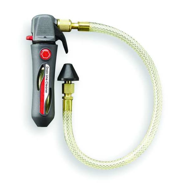
It is time for annual spring AC maintenance calls. One thing you should be doing is cleaning out the condensate line and checking to see that the condensate drain is working properly. The customer is paying you for a seasonal maintenance to avoid having problems – such as a mess caused by something as simple as a clogged drain line. If you can get to the condensate drain easily, you can blow it out with nitrogen using a rubber stopper with a 1/4” copper pipe and flare connection.

Gallo Gun


Another option is the Gallo Gun that uses CO2 charges. Both of these options require access to the drain opening inside the evaporator drain pan. The drain opening is usually accessible on cased coils by removing a panel on the front of the coil casing. Likewise, the drain opening for the coil in most heat pump air handlers can be accessed by removing the front panels.


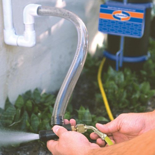
However, for coils in hard to reach places, or coils installed inside a plenum with no access panel, it may be easier to suck out the muck using a Sludge Sucker. The Sludge Sucker is installed on the drain outlet. Nitrogen pressure creates a vortex which makes a strong suction on the drain line, sucking out the water and muck in the entire drain system.
Uniweld Sludge Sucker


Foe some systems you may need to clean out the condensate line trap. If  the drain is already plugged, then chances are the trap is plugged. Most manufacturers require condensate line traps. The trap is designed to stop air from sucking in through the condensate line during operation. Unfortunately, because traps tend to trap stuff, they get blocked with crud. Most codes now require that condensate lines have clean-outs which allow the trap to be cleaned without cutting out the existing trap and replacing it. For many site built traps, this has been common for many years. The only practical way to clean them was actually to just replace them.

If you do have to cut out and replace a condensate trap, make sure that what you replace it with can be opened and cleaned. This can be done by installing tees in a couple of places where you would normally use ells and plugging or capping the unused branch. Alternatively, you can use a manufactured product such as the Rectorseal EZ Trap of the All-Access AA1 cleanout.
Rectorseal EZ Trap
All Access AA1


Another solution would be to remove the traditional trap and replace it with a product designed to provide a drain seal without trapping water. Three types are available – the Cost Guard condensate drain seal by Trent Technologies, the Air Trap by Des Champs Technologies, and the Rectorseal Waterless Kit for their EZ Trap. I will talk more about how these work in a future post.
Trent Technologies Cost Guard

Des Champs Air Traps
Rectorseal Waterless Kit


If the system you are working on does not have a safety overflow switch installed, consider adding one. The safety switch is typically wired in series with “Y” to prevent the outdoor unit from operating and creating more water.  Some are installed in the primary drain clean-out, and some are installed in the secondary drain port. They are inexpensive, easy to add, and help prevent property damage. In the case of coils installed on top of furnaces, they can prevent the destruction of expensive electronic components inside the furnace from an overflowing condensate drain.
Rectorseal Safety Switch in primary drain

Diversitech safety switch in secondary drain


Monday, May 9, 2016

Politics Poisons Working Relationships

This 2016 presidential election promises to be an especially exciting and event-filled campaign. Many people are bound to get caught up in the excitement and fury to come. However, please do not make the mistake of discussing politics at work. People can get emotionally wrought up in their politics, causing unkind remarks that are impossible to un-say. Discussing politics at work can poison a healthy working relationship.

Several years ago a student went to work for a local company. At first all was bliss. The student talked about how nice the owner was and how much he was learning. The company owner remarked on how smart the student was and how quickly he learned. Then all of a sudden the reports changed. The student now called the owner a racist bigot and the owner said the student was lazy and stupid. Digging a little deeper I discovered the core issue: one day at work the student had offered his negative opinion of then president Ronald Reagan. He had made the assumption that because both he and his employer were on friendly terms and were polite to each other, that they felt the same way regarding politics. However, the employer thought Reagan had saved the country. The ensuing discussion left both of them so angry that the student could no longer work there. The student really needed the job, and truth be told, the company really needed his help. Both parties lost a valuable working relationship because of a casual remark about politics.

If you are an employee, offering your opinion on politics to fellow workers or your boss can jeopardize your relationship. If you are the boss, think about the effect offering your opinion has on your employees. They can’t safely disagree – so you won’t likely get honest discussion. They may quietly agree, even if they don't agree. Or, they may decide you're a racist bigot and quit. And of course you should NEVER start a political discussion with customers. If the customer starts the discussion, agree with whatever they say and get out of the discussion as quickly as possible. Who loses if the customer gets upset because of political differences? You and your company.

I know you probably feel that the country’s existence depends upon your candidate winning. But the truth is whoever is elected president will be there four years, maybe eight years. Hopefully your career will extend far beyond eight years. The president will come and go and you will still be making the world a better place by keeping folks comfortable. So what happened to the two techs in the story? They are both doing fine – separately. I am sure that they support different candidates. They each are fine men, good techs, and do our trade proud – I just won’t discuss politics with them.

Wednesday, April 27, 2016

Pressure Transducers

On my last post I discussed common refrigeration pressure switches. As the name implies, these are switches which are opened and closed by pressure changes. They can make or break circuits, but they cannot indicate pressure. Pressure transducers are often used for electronic controls because they can actually indicate system pressures.

The word “transduce” means to change from one form to another. A pressure transducer turns pressure changes into analog electrical signal changes. This is most often a change in a DC voltage, typically 0 – 5 volts DC. This changing voltage can then be interpreted as a pressure by the electronic control to which it is connected.

The most common pressure transducers used in HVAC use a small stainless-steel diaphragm with strain gauges bonded to it. A change in pressure causes the diaphragm to bend, which causes the strain gauges to change resistance. These transducers have three leads: two are wired to DC+ and DC- and the third carries the signal. Pressure transducers ohm out like a potentiometer. On diagrams this looks like a potentiometer with a pressure bellows connected to the wiper arm. The resistance between the two leads that connect to DC voltage should stay the same regardless of the pressure. The third lead changes resistance relative to the two other leads as the pressure changes.


When the two other leads are connected to 5 volts DC, the signal connection will vary between 0 and 5 volts DC depending on the pressure. The control then interprets this voltage and controls the system based on the board’s program. If you want to check the transducer signal, read the voltage between the signal lead and DC- and then compare this voltage to a chart published by the manufacturer. Here are a couple of links to more information on presure transducers

Omega Transducers

Emerson Climate Technologies